A transistor is a semiconductor device that is commonly used as an amplifier or electronic control switch. It is an essential component for regulating the operation of computers, cell phones and all other modern electronic circuits.
Due to their fast response time and high accuracy, transistors can be used for a variety of digital and analog functions, including amplification, switching, voltage regulation, signal modulation, and oscillators.
Strictly speaking, transistors refer to all single components based on semiconductor materials, including diodes (two-terminal), triodes, field-effect tubes, and thyristors (the latter three are three-terminal).
Three-terminal transistors are divided into two main categories: bipolar transistors (BJTs) and field-effect transistors (FETs). The three terminals of a bipolar transistor are emitter, base and collector, and consist of N-type and P-type semiconductors; the three terminals of a field-effect transistor are source, gate and drain.
Transistors can be classified according to the following.
● Material
Transistors can be classified into silicon transistors and germanium transistors according to the semiconductor material. And according to polarity, these two types of transistors can be subdivided into germanium NPN-type transistors, germanium PNP-type transistors, silicon NPN-type transistors, and silicon PNP-type transistors.
●Manufacturing Process
According to the manufacturing process of transistors, there are diffusion type transistors, alloy type transistors, and planar type transistors.
●Current Capacity
Transistors can be divided into three groups according to their current capacity: low power transistors, medium power transistors, and high power transistors.
●Operating Frequency
There are low-frequency transistors, high-frequency transistors and ultra-high-frequency transistors according to their operating frequencies.
●Package Structure
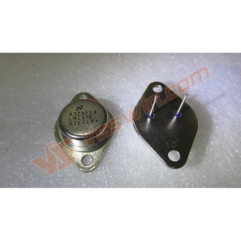
According to the package structure, transistors can be divided into metal encapsulated transistors, plastic encapsulated transistors, glass encapsulated transistors, surface mount transistors and ceramic encapsulated transistors.
● Function and Application
Transistors can be divided into low noise amplifying transistors, medium and high frequency amplifying transistors, low frequency amplifying transistors, switching transistors, Darlington transistors, high voltage transistors, band resistance transistors, damping transistors, microwave transistors, photoelectric transistors and magnetic transistors.
A semiconductor transistor is a semiconductor device that usually contains two PN junctions inside and three lead electrodes outside. Strictly speaking, transistors refer to all single components based on semiconductor materials, including diodes (two-terminal), triodes, field-effect tubes, and thyristors (the latter three are three-terminal).
Three-terminal transistors are divided into two main categories: bipolar junction transistors (BJTs) and field-effect transistors (FETs). The three terminals of a bipolar transistor are emitter, base and collector, and consist of N-type and P-type semiconductors; the three terminals of a field-effect transistor are source, gate and drain. The following discussion focuses on bipolar transistors, field effect transistors and some other typical types of transistors.

A bipolar junction transistor (BJT) is a device in which two PN junctions are combined by a certain process. In this context, "bipolar" means that both electrons and holes are involved in motion during operation. There are two combinations, PNP and NPN, with three external poles, collector, emitter, and base, respectively. The collector leads from the collector area, the emitter from the emitter area, and the base from the base area (middle).
The amplification effect of the BJT depends mainly on the transfer of the emitter current from the base region to the collector region. To ensure this transfer process, two conditions need to be satisfied.
● Internal conditions
The impurity concentration in the emitter region should be much larger than that in the base region, and the thickness of the base region should be small.
● External conditions
The emitter junction must be forward biased and the collector junction must be reverse biased.
Field effect transistor is a transistor that works by using the field effect principle of semiconductor. There are two main types of field effect transistors: junction FETs (JFETs) and metal oxide semiconductor FETs (MOSFETs).
The field effect is used to vary the direction or magnitude of an applied electric field perpendicular to the surface of the semiconductor to control the density or type of most carriers in the conducting layer (channel) of the semiconductor. The current in the channel is modulated by the voltage and the operating current comes from the majority carriers in the semiconductor.
Unlike BJTs, FETs have only one type of carrier (majority carrier) involved in the conduction process and are therefore also called unipolar transistors.
The advantages of the field effect transistor are.
High input impedance
Low noise
Limit frequency
Low power consumption
Simple manufacturing process
Good temperature characteristics
These characteristics make them widely used in various amplifier circuits, digital circuits, microwave circuits, etc. Silicon metal oxide semiconductor field effect transistors (MOSFETs) and GaAs metal oxide semiconductor field effect transistors (MESFETs) are the two most important field effect transistors, which are the basic devices for MOS large-scale integrated circuits and MES ultra-high-speed integrated circuits, respectively.
●Giant Transistor (GTR)
A giant transistor is a bipolar transistor that can withstand high voltages and high currents, so it can also be called a power BJT.
Its characteristics are.
○High voltage resistance
○High current
○Good switching characteristics
○Complex driving circuit and high driving power
The operating principle of GTR is the same as that of a normal bipolar junction transistor.
●Phototransistor
A phototransistor is an optoelectronic device consisting of a three-terminal device such as a bipolar transistor or a field effect transistor. Light is absorbed in the active region of the device to produce photogenerated carriers, which are amplified by an internal mechanism and produce photocurrent gain. Since phototransistors use three-terminal operation, it is easy to achieve electrical control or synchronization.
There are two main types of phototransistors: bipolar phototransistors and field-effect phototransistors. Bipolar phototransistors usually have higher gain but are not as fast as GaAs-GaAlAs bipolar phototransistors, which can have an amplification greater than 1000 and a response time greater than nanoseconds. Such phototransistors are commonly used in photodetectors or light amplification. Field-effect phototransistors have a fast response time (about 50 picoseconds), but their sensing area and gain are small and are often used as ultra-high-speed photodetectors.
Planar photodevices have a response time of tens of picoseconds and are suitable for optoelectronic integration.
● Electrostatic-sensing transistors
The electrostatic induction transistor (SIT) is actually a junction type field effect transistor. For low-power SITs used for information processing, they can be transformed into high-power SIT devices if we change their horizontal conductive structure to a vertical conductive structure.
The basic structure and symbol of SIT
SIT operates at a frequency comparable to or even higher than that of a power MOSFET, and its power capacity is greater than that of a power MOSFET. It is suitable for radar communication equipment, ultrasonic power amplification, pulse power amplification, and high frequency induction heating.
However, SIT is on when no signal is added to the gate and off when negative bias is added to the gate, making it inconvenient to use. In addition, SIT has a large on-resistance, which increases the loss, so it is not widely used in most power electronic devices.
●Single Electron Transistor
A single-electron transistor can record signals with one or several electrons.
With the development of semiconductor etching technology, the integration of large-scale integrated circuits is getting higher and higher. Currently, each memory cell of a general memory contains 200,000 electrons, while each memory cell of a single-electron transistor contains only one or a few electrons, which can greatly reduce power consumption and improve the integration of integrated circuits.
In 1989, JHFScottThomas and his partners discovered Coulomb blocking in an experiment. In their tests, they tried to make small-area metal electrodes on a two-dimensional electron gas at the interface of a modulation-doped heterojunction, which allowed them to obtain quantum dots with small capacitance (10 to 15 Farads). formed in the electron gas. When a voltage is applied, no current will flow through the device until the voltage is large enough to cause a change in electron charge. Thus, the current-voltage relationship is not linear but stepwise. The experiment was the first in history to manually control the motion of electrons and provided the experimental basis for the fabrication of single-electron transistors.
In order to increase the operating temperature of single-electron transistors, the size of the quantum dots must be smaller than 10 nm, which is an urgent problem for laboratories around the world to solve.
The transistors in the circuit are mainly crystal diodes, crystal transistors, thyristors and field-effect tubes, of which crystal transistors and diodes are most commonly used. Then how to correctly determine the diode and transistor good or bad?
● Performance: good or bad
The first step is to determine whether the material of the crystal diode is silicon or germanium. Use a multimeter to measure its forward resistance, and another multimeter to measure the voltage drop. Generally the forward voltage drop of a germanium tube is between 0.1-0.3V, and the forward voltage drop of a silicon tube is usually between 0.6-0.7V.
In addition, the difference between the forward and reverse resistance of the diode should be as large as possible. A crystal diode can be considered a good diode if its forward resistance is in the hundreds to thousands of ohms and its reverse resistance is in the tens of thousands of ohms or more.
● Electrode: positive or negative
In addition, the positive and negative electrodes of a diode can be determined at the same time. When the resistance being measured is several hundred or several thousand ohms, it should be determined as the positive resistance of the diode. At this time, the negative meter pen connects to the negative pole, the positive meter pen connects to the positive pole. In addition, if the forward and reverse resistance is infinity, it means that there is an internal break; if the forward and reverse resistance is zero, indicating a short circuit.
● Test amplification capability
Crystal transistor is mainly used for amplification, so how to determine its amplification capacity?
First of all, the multimeter gear set to R × 100 or R × 1 K. When we measure the NPN tube, the positive pen connects the emitter, the negative pen connects the collector. The resistance under test should generally be a few thousand ohms or more.
Then connect a 100kΩ resistor in series between the base and collector. At this point, the resistance value measured by the multimeter should be significantly reduced. The larger the change, the stronger the amplification capability of the transistor. If the change is very small or even no change, it indicates that the amplification ability of the transistor is weak or no amplification ability.
● Judgment electrode
1. Find the base
First, connect the red meter pen to any of the pins, and measure the other two pins separately with the black meter pen.
See if you can measure two small resistances. If not, connect the black meter pen to one pin, and measure the red meter pen in contact with the other pins until you get two small resistances.
When two small resistors are found, the fixed test line used at this time is the base. If the fixed test pen is black, the transistor is of NPN type; if the fixed test line is red, the tube is a PNP type transistor.
Note: Germanium tubes are measured with R×100, and silicon tubes are measured with R×1k.
2. Determine the emitter and collector
Use a multimeter to measure the resistance of both poles except the base. Replace the test line and remeasure.
If it is a germanium tube, use the smaller resistance to determine. When a smaller resistance is obtained, for PNP transistors, the black meter pen is connected to the emitter and the red meter pen is connected to the collector. If it is an NPN type, the black meter pen is connected to the collector and the red meter pen is connected to the emitter.
If it is a silicon transistor, use a larger resistor. For PNP type, the black meter pen is connected to the emitter, while the red meter pen is connected to the collector. And for NPN transistors, the black and red pens are connected to the collector and emitter, respectively.
In addition, we can also measure the forward resistance of each of the two PN junctions. The one with the higher forward resistance is the emitter and the other is the collector.
In the internal structure of an ordinary Darlington transistor, two or more collectors of the transistor are connected together, and there are multiple emitter junctions between the base and emitter.
● Forward and reverse resistance test
Measurement is performed using a multimeter with R×1kΩ or R×10kΩ.

Under normal conditions, the forward resistance between collector and base is similar to the value of ordinary silicon transistor collector, which is 3-10kΩ, and the reverse resistance value is infinite. The forward resistance value between emitter and base is 2 to 3 times of that between collector and base, and the reverse resistance value is also infinite.
Theoretically, the positive and negative resistance between collector and emitter should be close to infinity. If the positive and negative resistance values between the collector and emitter of a Darlington transistor are close to zero, or the resistance value between the base and emitter or between the base and collector is zero, it indicates that the tube has gone bad. If the forward and reverse resistance between the base and emitter or between the base and collector is measured to be infinity, it indicates the presence of an open circuit.
Note: When we measure the NPN tube, the black meter pen is connected to the base; when the PNP tube is detected, the black meter pen is connected to the collector.
High power Darlington transistor has a protection circuit consisting of a current-continuing diode and shunt resistor on the basis of ordinary Darlington transistor, which may affect the measurement data.
●Testing method I
Measure the forward and reverse resistance of the Darlington collector junction (between collector and base) with the R×1kΩ or R×10kΩ range of a multimeter. Under normal circumstances, the base of the NPN tube connected to the black pen, the forward resistance value should be very small, between 1 ~ 10kΩ, the reverse resistance value should be close to infinity. If the measured forward and reverse resistance values are very small or infinity, it means that the tube has been short-circuited or open-circuit damaged.
● Detection method 2
Use the multimeter R × 100Ω file to measure the forward and reverse resistance between the emitter and the base. The normal value is a few hundred ohms to a few thousand ohms. If the measured resistance is 0 or infinity, the tube under test is damaged.
● Detection method 3
Measure the forward and reverse resistance between the emitter and collector with a multimeter R×lkΩ or R×10kΩ. Under normal circumstances, the forward resistance value should be 5-15kΩ, and the reverse resistance value should be infinity, otherwise the collector and emitter (or diode) are damaged or open circuit.
Note: When measuring the NPN tube, the black pen connects to the emitter and the red pen connects to the collector; when measuring the PNP tube, the black pen connects to the collector and the red pen connects to the emitter.
In this article, we have firstly understood the general classification method and the main typical types of transistors. Then the test methods of crystal diodes and crystal transistors, including the means of performance judgment and electrode determination, were introduced. Finally, the test methods for common and high-power Darlington transistors are discussed. I hope this article is useful to you!
Hot News