A PNP type triode is a triode consisting of two P-type semiconductors sandwiched by an N-type semiconductor, so it is called a PNP type triode. It can also be described as a transistor in which current flows from the emitter E.
PNP-type transistors have the highest emitter potential and the lowest collector potential, UBE < 0.

Triode by structure, can be divided into NPN-type transistors and PNP-type transistors.
IE = (amplification +1)*IB and ICB are not related to the transistor conduction, ICB = 0 ICB>0, there may be a problem with the transistor, so the transistor in normal operation, regardless of whether it is working in the amplification area or saturation area ICB = 0
When UEB>0.7V (silicon) (germanium 0.2V), RC/RB < amplification, the transistor works in the saturation zone, and vice versa, it works in the amplification zone.
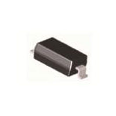
9012 is a very common crystal transistor, which is often seen in radio and various amplification circuits, and has a wide range of applications, it is a PNP type small power transistor
Collector-emitter voltage -30V
Collector-base voltage -40V
Emitter-base voltage -5V
Collector current 0.5A
Frequency 150MHZ minimum
Magnification: D64-91 E78-112 F96-135 G122-166 H144-220 I190-300
NPN type triode is a triode composed of two N-type semiconductors sandwiched between a P-type semiconductor; also known as a crystal triode, it can be said that it is the most important device in electronic circuits. Triode is the most important device in electronic circuits, its main function is current amplification and switching role, it can turn a weak electrical signal into a signal of a certain strength, of course, this conversion still follows the conservation of energy, it is only the energy of the power supply into the energy of the signal.
9013 is a NPN type silicon small power transistor it is very common crystal transistor, in the radio and a variety of amplification circuit often see it, the application range is very wide, it is NPN type small power transistor. It can also be used as a switching transistor. Note: 9013 power is less than 9014, mutual replacement should be considered when the current size.
Collector-emitter voltage 25V
Collector-base voltage 45V
Emitter-base voltage 0.7V
Collector current Ic Max 0.5A

When the base voltage UB has a small change, the base current IB will also have a small change, controlled by the base current IB, the collector current IC will have a large change, the larger the base current IB, the larger the collector current IC.
Conversely, the smaller the base current, the smaller the collector current, i.e., the base current controls the change of collector current. But the change in collector current is much larger than the change in base current, which is the amplification of the triode. the ratio of the change in IC to the change in IB is called the amplification of the triode β, the amplification of the triode β is generally in the tens to hundreds of times.
1. Definition
NPN-type transistor consists of three semiconductors, including two N-type and a P-type semiconductor, the middle is a P-type semiconductor, the two sides are two N-type semiconductor.
NPN-type transistors are the most important devices in electronic circuits, the main function is the current amplification and switching function.
A PNP-type triode is a triode composed of two P-type semiconductors sandwiched between one N-type semiconductor, hence the name PNP-type triode. Or described as a transistor with current flowing from the emitter E.
2. PN junction components in different directions
The direction of the two PN junctions are different, PNP for the common cathode, that is, the two PN junctions of the N junction connected to the base.
NPN on the contrary, the two P junctions of the NPN are the collector and emitter, respectively. Circuit diagram marked with inward arrows for the triode.
3. The structure is different
PNP-type transistor is a transistor consisting of two P-type semiconductors sandwiched between N-type semiconductors, called PNP-type PNP-type transistor.
NPN-type transistors are composed of two N-type semiconductors and a P-type semiconductor sandwiched between them, called NPN-type transistors.
The main difference between NPN and PNP is the current direction and the positive and negative voltage.
Method 1.
Identify the base B
Set the digital multimeter to the diode file, the red pen fixed any connection to a pin, with the black pen in turn contact the other two pins, if the two display values are less than 1V or are displayed overflow symbol "1", the red pen connected to the pin is the base B. If in the two tests, a display value less than 1V, another display overflow symbol "1", indicating that the red pen connected to the pin is not the base B, then you should change to other pins to re-measure until you find the base B.
Distinguish NPN tube and PNP tube
Use the digital multimeter diode file. After confirming the base B according to the above operation, connect the red meter pen to the base B and use the black meter pen to contact the other two pins one after another. If both show 0.500 ~ 0.800V, the tube under test belongs to the NPN type; if both show the overflow symbol "1", it shows that the tube under test belongs to the PNP tube.
Method 2.
Determine the base.
Use a multimeter R × 100 or R × 1k block to measure the tube three electrodes in each of the two poles between the positive and negative resistance value. When the first meter pen to an electrode, and the second meter pen has contact with the other two electrodes are measured low resistance, the first meter pen is connected to the electrode that is the base b.
At this point, pay attention to the polarity of the multimeter pen, if the red pen is connected to the base b. Black pen is connected to the other two poles, respectively, the measured resistance are smaller, it can be determined that the tube under test for PNP-type transistors; if the black pen is connected to the base b, the red pen is in contact with the other two poles, respectively, the measured resistance is smaller, then the transistor under test for NPN-type tubes such as 9013, 9014, 9018.
(1). Cutoff state
Triode base without bias voltage or reverse bias voltage, so that the BE pole cut-off (BE pole and diode characteristics of the same, need to add 0.7V forward bias to conduct), the base current IB = 0, because IC = β IB, so IC = IE = 0, at this time between the CE pole is equivalent to a break, the load no current.

(2). Saturation state
When the base of the transistor to join the large current, because IC ≒ IE = β × IB, the emitter and collector current is also very large, at this time, the voltage drop between the collector and the emitter is very low (VCE for 0.4V or less), the significance of the equivalent of the collector and the emitter between fully conductive, this state is known as the transistor saturation.

Further Reading: C945 Transistor NPN: Description, Function and Switch
Hot News