The C1815 transistor is a widely used bipolar junction transistor (BJT) known for its versatility and reliability. With its compact size and high gain, the C1815 transistor finds applications in various electronic circuits and systems.
This article serves as a comprehensive guide to the C1815 transistor, providing valuable information on its pinout configuration, equivalents, and common uses. Whether you are an electronics enthusiast, hobbyist, or professional, understanding the pinout, equivalents, and applications of the C1815 transistor will enable you to harness its potential in your electronic projects.
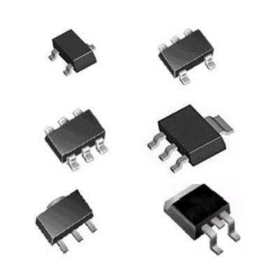
The C1815 transistor is a popular NPN (Negative-Positive-Negative) bipolar junction transistor (BJT) used in a wide range of electronic circuits. It belongs to the 2SC1815 series of transistors and is commonly available in packages such as TO-92, SOT-23, and SMD.

Transistors are fundamental electronic components that are widely used for amplification, switching, and signal processing purposes. The C1815 transistor, in particular, is a small-signal transistor, meaning it is primarily used in low-power applications.
The C1815 transistor typically has three pins: the emitter (E), base (B), and collector (C). The emitter (E) is usually the leftmost pin when viewing the flat side of the transistor with the pins facing down. The base (B) is in the middle, and the collector (C) is on the right.


Transistor Type: NPN (Negative-Positive-Negative) bipolar junction transistor.
Maximum Ratings:
Collector-Base Voltage (VCBO): 60V
Collector-Emitter Voltage (VCEO): 50V
Emitter-Base Voltage (VEBO): 5V
Collector Current (IC): 150mA
Power Dissipation (Pd): 400mW
Electrical Characteristics (at 25°C and VCE = 5V, IC = 10mA):
DC Current Gain (hFE): Typically 70 to 700
Collector-Emitter Saturation Voltage (VCE(sat)): Typically 0.2V
Base-Emitter Voltage (VBE): Typically 0.6V
Transition Frequency (fT): Typically 100MHz
Package Types: The C1815 transistor is available in various package types, including:
TO-92: A through-hole package with three leads.
SOT-23: A small surface mount package with three leads.
SMD: Surface mount devices in different package styles.
Operating Temperature Range: -55°C to +150°C.
Application: The C1815 transistor is commonly used in low-power amplifier circuits, audio amplifiers, oscillators, voltage regulators, and switching applications.
A1015 (2SA1015)
The C1815 transistor finds applications in a variety of electronic circuits. Its common uses include amplification in low-power audio and small-signal amplifier circuits, oscillators for generating stable waveforms, voltage regulators for maintaining consistent power output, and as a switch in digital and analog circuits for controlling current flow and component activation. The C1815's versatility makes it suitable for a range of applications where amplification, signal processing, and switching functionalities are required in low-power settings.
Sensor Circuits
Audio Preamplifiers
Audio amplifier
Load switching at 150mA or less
RF circuits
The C1815 transistor can be utilized as a switch in electronic circuits. When used as a switch, the C1815 operates in two modes: cutoff mode and saturation mode.

In cutoff mode, the base-emitter junction is reverse-biased, resulting in no current flowing from the collector to the emitter. This corresponds to the "off" state of the switch.
In saturation mode, the base-emitter junction is forward-biased, allowing current to flow from the collector to the emitter. This corresponds to the "on" state of the switch.
By controlling the biasing of the base-emitter junction, the C1815 transistor can effectively control the flow of current through the collector-emitter path, enabling or disabling the operation of connected components.
To use the C1815 as a switch, a small current is applied to the base terminal to forward-bias the base-emitter junction and turn the transistor "on." This allows a larger current to flow through the collector-emitter path, activating the connected load. Conversely, when no current is applied to the base terminal, the transistor remains in the "off" state, and the connected load is effectively deactivated.
By utilizing the C1815 transistor as a switch, it is possible to control the operation of various components and circuits, making it suitable for applications such as digital logic, automation, and power control systems.
To test a C1815 transistor, you can follow these general steps:
Step1. Identify the pinout: Determine the pin configuration of the C1815 transistor. Typically, the transistor will have three pins: the emitter (E), base (B), and collector (C). The datasheet or markings on the transistor can help you identify the pins.
Step2. Set up the test circuit: Create a simple test circuit using a power supply, resistor, and multimeter. Connect the positive terminal of the power supply to the collector pin, the emitter pin to the negative terminal, and the base pin to a resistor.
Step3. Measure resistance: Set your multimeter to the resistance (ohms) mode and measure the resistance between the base and emitter pins. You should see a high resistance value, indicating an open circuit (off state). Reverse the leads of the multimeter and check the resistance again. You should get a low resistance value, indicating a forward-biased junction (on state).
Step4. Test with a signal generator (optional): If available, you can also test the transistor's amplification capabilities using a signal generator. Connect the base pin to the signal generator through a coupling capacitor and measure the output signal at the collector pin using an oscilloscope. Apply various frequencies and input signal levels to observe the transistor's response.
Step5. Current and voltage measurements: You can also measure the current flowing through the collector-emitter path and the voltage across the base-emitter junction using a multimeter. Apply appropriate voltage and current levels to test the transistor within its specified ratings and observe the readings.
The C1815 transistor is a part of the 2SC1815 series and does not have an exact equivalent within the same series. However, there are other transistors that can serve as functional equivalents or substitutes for the C1815, depending on the specific requirements of your circuit. Some commonly suggested equivalents or substitutes for the C1815 include:
💡 2N3904: A widely used NPN transistor with similar characteristics to the C1815. It is available in various package types and is suitable for general-purpose amplification and switching applications.
💡 BC547: Another commonly used NPN transistor that can be used as a substitute for the C1815. It has similar electrical characteristics and is suitable for low-power amplification and switching applications.
💡 KSC1815: This is a variant of the C1815 transistor and is designed to have similar characteristics. It can be used as a direct replacement for the C1815 in many applications.
Free Download 2sc1815 datasheet.pdf here>>
In conclusion, the C1815 transistor is a versatile and widely used component in electronic circuits and systems. With its reliable performance, compact size, and availability, it has become a popular choice for a range of applications.
By referring to the pinout diagram, exploring equivalent options, and understanding its common uses, you can effectively incorporate the C1815 transistor in your electronic projects. Whether you are amplifying signals, switching circuits, or designing audio applications, the C1815 transistor offers a dependable and efficient solution. Stay updated with the latest advancements and datasheets to make the most of the C1815 transistor in your future electronic endeavors.
Hot News