A silicon-controlled rectifier (SCR) is a type of thyristor, which is a semiconductor device used for controlling the flow of electric current. The SCR is a four-layer solid-state device with three terminals: an anode, a cathode, and a gate.
The operation of an SCR is based on the principle of a p-n junction diode. When a positive voltage is applied to the anode with respect to the cathode, the p-n junction between the anode and the gate becomes forward-biased, allowing a small current to flow into the gate terminal. This current triggers a self-sustaining avalanche breakdown process, which allows a large current to flow from the anode to the cathode.
Once the SCR is turned on, it continues to conduct current even if the voltage across the anode-cathode terminals is reduced to zero. The SCR can be turned off by applying a negative voltage to the gate terminal or by reducing the current flowing through the device to below its holding current.
SCRs are commonly used in power electronics applications such as motor control, lighting control, and power supplies. They offer high efficiency, reliability, and cost-effectiveness compared to other switching devices.
The BT151 SCR is a semiconductor device, also known as a thyristor, so this assembly includes four alternating N-layers and P-type material.The BT151 SCR is housed in a plastic case and is primarily intended for applications requiring high thermal cycling performance and high bi-directional blocking voltage capacity.

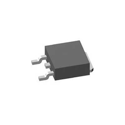
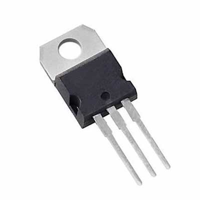
The BT151 is a 12A medium power SCR SCR in a TO-220 package. This SCR is used for switching standard power AC or DC loads and managing high DC signals, primarily for power switching purposes.
| Pin number: | Pin name: | Pin description: |
| 1 | Cathode | Conventional current flows out of the cathode |
| 2 | Anode | Conventional current flows into the anode |
3 | Gate | Controls conduction between anode and cathode |
| 4 | Tab | Eletrically connected to the anode |
The BT151 is a type of SCR (Silicon Controlled Rectifier) that has several features which make it useful for controlling high-voltage and high-current loads in a variety of applications. Here are some of the key features of the BT151 SCR:
Features and specifications of the BT15 thyristor include the following.
With thyristor and thyristor and other functions
Good bi-directional voltage blocking capability
High inrush current capacity
High thermal cycling performance
High reliability
Peak breaking voltage of 650V
Standard pass-state current is 7.5A
RMS pass-state current is 12A
Gate trigger current range of 1mA-15mA
High thermal cycling performance
High blocking voltage and bi-directional
Inrush current rating of 132 amps
Gate trigger current is 15mA maximum
Maximum hold current of 20mA
Peak shutdown current repetition of 0.5mA
Maximum reverse voltage repetition of 500V
Gate trigger voltage maximum of 1.5 volts
Maximum pass state voltage is 1.75 volts
Repeated maximum forward blocking voltage of 500 volts
High voltage and current rating: The BT151 SCR has a maximum rated voltage of 600 volts and a maximum rated current of 12 amperes, making it suitable for use in applications that require high voltage and current control.
Low gate triggering current: The BT151 SCR has a low gate triggering current, typically around 20 milliamperes. This means that it can be triggered with a low-level control signal, which makes it ideal for use in low-power control circuits.
High surge current capability: The BT151 SCR has a high surge current capability, which allows it to handle short-duration current surges that can occur in certain types of applications. This feature makes it suitable for use in applications such as motor control and power supplies.
Low holding current: The BT151 SCR has a low holding current, typically around 5 milliamperes. This means that once the SCR has been triggered, it can continue to conduct current with very little input power, making it highly efficient.
Operating temperature range: The BT151 SCR can operate at temperatures up to 125 degrees Celsius, which makes it suitable for use in high-temperature environments.
As you know, the operating principle of a SCR rectifier is that once biased or triggered at the gate terminal of the SCR, it begins to conduct. Since it is a unidirectional element, the current will flow in one direction.

In addition, SCRs are transistors, but once they are triggered they can be latched, which means that the gate signal has been disconnected. They wait in conduction until the anode-cathode current drops below a fixed value called the holding current.
Choose the appropriate circuit: Determine the type of circuit you need to control your load. This may involve designing a new circuit or modifying an existing one.
Connect the BT151 SCR: Connect the BT151 SCR to the circuit by soldering or screwing it into place. Be sure to observe the correct polarity of the device. The anode (A) should be connected to the positive side of the circuit, and the cathode (K) should be connected to the negative side of the circuit.
Apply gate voltage: Apply a gate voltage to the gate (G) terminal of the BT151 SCR to trigger the device. The gate voltage should be within the gate triggering voltage range of the BT151 SCR, typically 0.8 to 1.5 volts. The gate current required to trigger the device is typically around 15 mA.
Control the load: Once the BT151 SCR is triggered, it will conduct current from the anode to the cathode until the current falls below the holding current of the device, typically around 20 mA. This allows the BT151 SCR to be used for controlling the flow of current through a load, such as a motor or a heating element.
Protect the device: Be sure to protect the BT151 SCR from overvoltage and overcurrent conditions that may damage the device. This may involve adding protective components such as diodes, fuses, or varistors to the circuit.
It is important to note that while these SCRs have similar ratings and characteristics to the BT151, they may not be exact replacements. It is recommended to consult the datasheets and application notes for any replacement SCR to ensure proper compatibility with your circuit.
The BT151 SCR is a versatile semiconductor device that can be used in a variety of applications. Here are some common applications of the BT151 SCR:
Motor Control
Ignition and protection circuits
Static switching
In the domestic lighting, static switching and heating industries
For applications requiring maximum thermal cycling performance and bi-directional positive break voltage capacity
CDI (Capacitive Discharge Ignition)
Voltage regulation
High junction temperature capability
AC voltage control: The BT151 SCR can be used to control the voltage of AC power supplies, which makes it useful for applications such as motor speed control, lamp dimming, and power supplies.
AC power switching: The BT151 SCR can be used to switch high-power AC loads, such as heaters, furnaces, and other industrial equipment.
Battery charging: The BT151 SCR can be used in battery charging circuits, where it can control the current and voltage applied to the battery for efficient and safe charging.
Welding: The BT151 SCR can be used in welding machines to control the current flow and voltage applied to the welding electrodes.
Power supplies: The BT151 SCR can be used in power supplies to control the voltage and current output, making it useful in applications such as computer power supplies, LED lighting, and battery chargers.
Temperature control: The BT151 SCR can be used in temperature control circuits, where it can control the amount of heat applied to a device or system.
Summary
The above is an introduction to the basic content of the BT151 SCR, mainly including its pin configuration, specifications and circuit applications. It is easy to see that BT151 is a medium-power SCR rectifier mainly used for power switching, similar to a transistor, but BT151 can stay on when triggered, even if the signal at the gate terminal is broken.
In addition, the BT151 SCR waits in conduction until the current flowing from the anode to the cathode is below a fixed value called the holding current.
Hot News