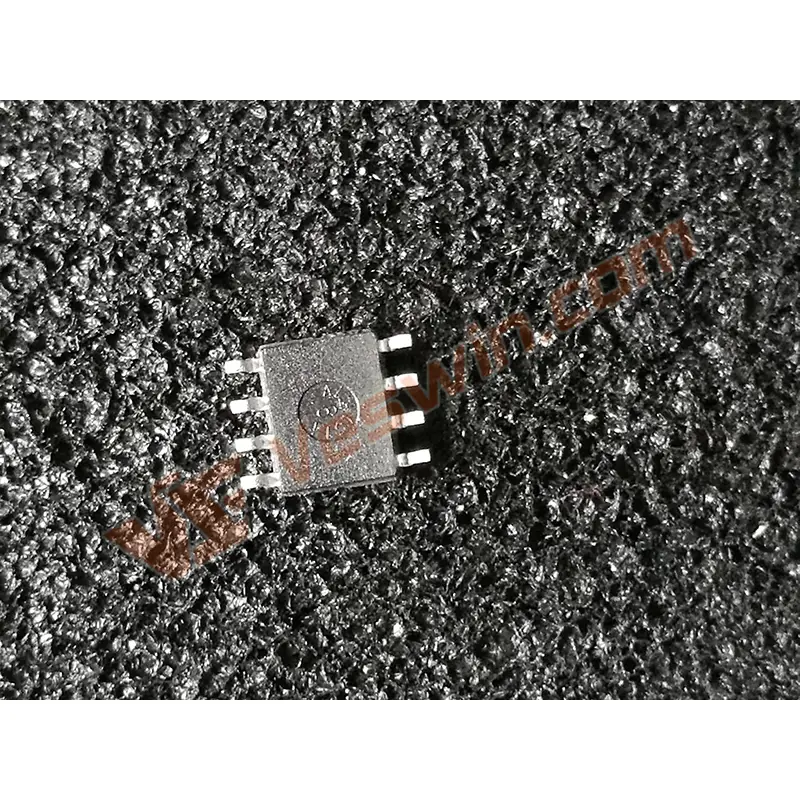
ADT75 is a digital temperature sensor introduced by Analog Devices. It has a built-in highly integrated temperature sensor with a rated operating temperature range of -55 ° C to + 125 ° C, which can accurately measure temperature. It also contains a 12-bit ADC to monitor and digitize the temperature value. The resolution can reach 0.0625 ° C, the power consumption is low, and the operating voltage range is 3 V "5.5 V. If the operating voltage is 3.3 V, its typical The current value is 300 μA; in the shutdown mode, the typical current value is only 3 μA. ADT75 is a complete digital temperature sensor, which integrates the sensor and analog-to-digital converter, which can greatly simplify the design of the temperature test system and improve the system. Integration.
Built-in 12-bit A / D converter;
The maximum temperature error is ± 1 ℃, and the temperature resolution is 0.0625 ℃;
SMBus / I2C compatible interface;
Operating temperature range is -55 ℃ "+ 125 ℃;
Over temperature indicator;
Reduce power consumption with shutdown mode;
Typical power consumption at 3.3 V operating voltage is 69 μW;
8-lead MSOP and SOIC packages.

It mainly includes temperature sensor, Σ-Δ regulator, 4 data registers (temperature data register, configuration register, THYST setting register and TOS setting register) and an address pointer register, digital comparator, SM-Bus / I2C string Line interface, etc. The working process is as follows: The temperature sensor collects the temperature, generates a precise voltage proportional to the absolute temperature, compares it with the internal reference voltage, inputs it into a precise digital regulator, and converts it into data with an effective accuracy of 12 bits. The measured temperature value is compared with the limit value. If the measured value exceeds the limit, the OS / ALERT pin outputs the limit information.
ADl75 contains 5 registers: 4 data registers and 1 address pointer register. The configuration register is the only 8-bit data register, and the rest are 16-bit. The temperature data register is the only read-only data register. At power-on, the address pointer register is set to Ox00, and the pointer points to the temperature data register.
(1) Address pointer register
The 8-bit write register stores an address that points to one of the four data registers and selects single-step mode. The single-step mode can reduce power consumption. When the single-step mode is started, the ADT75 immediately enters the shutdown mode. When VDD is 3.3V, the current consumption is 3μA; when VDD is 5V, the current consumption is 5.5μA. P0 and P1 select the data register to which data bytes are written or read. PO, Pl and P2 select single-step mode by writing 04H to this register. The remaining bits of this 8-bit register are set to zero.
(2) Temperature data register
The 16-bit read-only register stores the temperature value measured by the built-in temperature sensor. It is stored in two's complement mode, with the MSB as the temperature mark bit. When reading a register, read the upper 8 bits first, then the lower 8 bits.
(3) Configuration register
The 8-bit read / write register configures various modes for the ADT75, such as shutdown, overtemperature interrupt, single step, SMBus alarm enable, OS / ALERT pin polarity, and overtemperature error queue.
(4) THYST setting value register
This 16-bit read / write register holds the temperature hysteresis limit in 2 interrupt modes. The temperature limit value is stored in two's complement mode, and the MSB is used as the temperature flag. When reading from this register, the upper 8 MSBs are read first, and then the lower 8 LSBs are read. The default setting of THYST is + 75 ° C.
(5) TOS fixed value register
This 16-bit read / write register stores over-temperature limit values in two interrupt modes. Temperature limits are stored in two's complement. When reading from this register, the upper 8 MSBs are read first, and then the lower 8 LSBs are read. The default setting of TOS is + 80 ° C.
Temperature is one of the main controlled parameters in the measurement and control system. In practical applications, it is often necessary to control the temperature to keep it within a certain range. In the past, in actual measurement and control systems, thermistors or thermocouples were used to measure temperature. This temperature acquisition circuit sometimes requires a cold junction compensation circuit, which increases the complexity of the circuit; and the circuit is susceptible to interference, making the collected data inaccurate.
In a traditional temperature measurement and control system, a thermocouple or a thermistor is used to collect the temperature, and the tiny signal detected by the preamplifier circuit is converted into an ADC convertible signal. At the same time, A / D is performed after cold junction temperature compensation. Conversion, so as to digitize the analog temperature signal, as shown in Figure 3.
The characteristics of this traditional circuit are that more components are needed, the circuit occupies a large space, the circuit is susceptible to interference, the debugging workload is large, the circuit integration is poor, and the error is large.
ADT75 is a complete digital temperature sensor, which integrates the sensor and analog-to-digital converter. The use of ADT75 greatly simplifies the design of the temperature test system. The circuit integration is high, the space occupied is small, the accuracy is high, and the debugging workload is greatly reduced.
Application examples
Direct-cooled electric freezer has relatively few parts, the equipment is not prone to failure, and the refrigeration is relatively rapid. It uses the natural convection of air in the freezer to cool food. The evaporator is often installed in the upper part of the freezer. The air around the evaporator must exchange heat with the evaporator, and the air circulates naturally and convectively, so as to achieve the purpose of refrigeration. In actual use, the temperature of the electric freezer should be maintained at a set value, which requires automatic adjustment using a temperature measurement and control system. The temperature control principle is to control the start and stop of the refrigeration compressor according to the temperature of the evaporator, so that the temperature in the freezer is maintained within a set temperature range.
In the design of the direct-cooling type electric freezer temperature measurement and control system, the AT89C51 type single-chip microcomputer is used as the core, and the ADT75 is used to form a temperature control circuit. The circuit hardware design is simple, the power consumption is low, and the practicability is strong. The hardware interface circuit of ADT75 and AT89C51 is shown as in Fig.

In the circuit, connect the SMBus / I2C serial data input / output terminal SDA of the ADT75 to the P11 pin of the microcontroller, the serial clock input terminal SCL sends high and low levels in turn from the P10 pin, and the 10 kΩ resistor is the Pull the resistor; ADT75 uses the comparison mode. When the OS / ALERT output is set to low level, the buzzer connected to it will alarm the temperature. When A2, Al and A0 are grounded in the design, the address of SMBus / I2C is 1001000. According to the measured temperature value, the system completes the PID calculation inside the microcontroller, and then controls it through an external temperature control device.
The refrigeration compressor is started and stopped to adjust the temperature to keep the temperature in the electric freezer within a certain set range.
1 Protocol operation mode of serial bus
The master device (such as a single chip microcomputer, see Figure 4) starts the data conversion by setting the start condition. The ADT75 serial data line SDA defines the high-to-low conversion, and the serial clock line SCL is always high.
The ADT75 pulls the data line low before the 9th clock pulse and waits for data to be read or written. If the R / W bit is 0, write data to the ADT75. If the R / W bit is 1, data will be read from the ADT75.
Data is transferred to the serial bus in the order of a sequence of 9 clock pulses. In write mode, the master will pull the data line high during the 10th clock pulse to the stop state. In read mode, the microcontroller will pull the data line high during the low period before the 9th clock pulse.
2 ADT75 writing method
ADl75 has 2 different writing methods.
(1) Register write address
In order to read data from a specific register, the address pointer register must contain the register address. If this address is not included, the correct address must be written to the address pointer register by performing a single-byte write operation.
(2) Write data to the register
The configuration register is 8 bits, so only 1 byte of data can be written to this register. The data bytes written to the configuration register include the serial bus address, the data register address is written to the address pointer register, and then the data byte is written to the selected data register. Both the THYST register and the TOS register are 16 bits, so 2 data bytes can be written to these registers.
3 ADT75 readout method
For the configuration register, read data from the ADT75 as a single-byte data. For the temperature data register, the THYST register, and the TOS register, read data from the ADT75 as a double-byte data. To read data from other registers, you need to set the relevant register address to the address pointer register.
4 Working Mode in Over Temperature Mode
The ADT75 has two over-temperature modes, namely compare mode and interrupt mode.
(1) Comparison mode
In comparison mode, when the measured temperature drops below the temperature limit value stored in the THYST setting register, the OS / ALERT pointer will return to the invalid state again. In the comparison mode, there is no need to reset the OS / ALERT state when the ADT75 is set to the shutdown mode.
(2) Interrupt mode
In interrupt mode, the OS / ALERT pin enters the inactive state only when data is read from the ADT75 register. When the measured temperature is lower than the set value stored in the THYST setting register, the OS / ALERT pin returns to the active state. Once the OS / ALERT pin is reset, it will return to the active state again only when the temperature is higher than the value set in the TOS setting register.
5 Multi-circuit operation
Under the control of a master device, up to eight ADT75s can be connected to an SMBus / I2C bus. Like all SMBus / I2C compatible devices, ADl75 has a 7-bit serial address. , A1 and A0), there are 8 different address options. If multiple ADT75s are not required to work together, the A2, Al, and A0 pins are grounded.
In the hardware design of the direct-cooling type electric freezer temperature measurement and control system, the ADT75 can fully meet the requirements of temperature collection, and it is also very convenient to use. Because the external interface circuit of the temperature detection circuit is simple, the serial interface occupies less microcontroller port lines, and has excellent performance, low power consumption and good reliability, so the design and operation have achieved very satisfactory results.
Hot News
